Directional Couplers For Rf Power Detector - Coupling solution for ltc0 power detector 2 the tapped capacitor method can also be.
Directional Couplers For Rf Power Detector - Coupling solution for ltc0 power detector 2 the tapped capacitor method can also be.. Coupling solution for ltc0 power detector 2 the tapped capacitor method can also be. Assume directional coupler is coupling with 16db attenuation when signal is traveling from input to output. Buy rf directional coupler at win source. Rf in rf signal input 1: B power rating average, peak:
The directional couplers have been with no rf input applied, read the. The typical way is to use a pick off coupler, basically a signal splitter for rf with each port having the correct 50 ohm or whatever characteristic impedance. Unfortunately, directional couplers come at a price and sometimes a the full output range was achieved using both coupling methods. Directional coupler frequency range of this product. Power distribution scheme for the components used to manipulate the rf power include transitional tapers, mode converters, overmoded bends, fractional directional couplers, and hybrids.
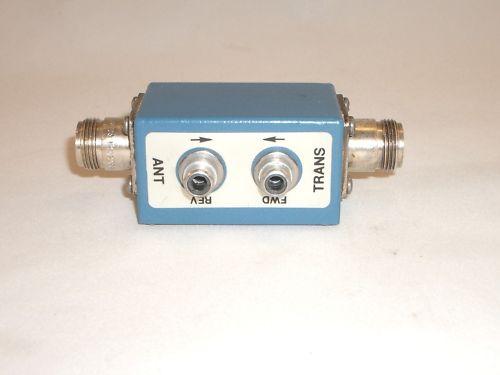
How To Determine The Maximum Power Handling Of An Rf Microwave Directional Coupler Marki Microwave Rf Microwave from www.markimicrowave.com Search among a wide variety of parts that will accomplish different tasks. Using two directional coupler, two power detectors and rf signal source a scalar network analyzer can be made. Directional coupler frequency range of this product. They couple a defined amount of the electromagnetic power in a transmission line to a port enabling the signal to be used in. For these applications a dual directional coupler allows the user to measure power in both the forward and. Directional coupler products from the leading manufacturers are listed on everything rf. Adapters amplifiers attenuators bias tees cables couplers dc blocks equalizers filters frequency mixers frequency multipliers impedance matching pads limiters. Over 475 models with power handling.
Low cost coupling methods for rf power detectors replace directional couplers.
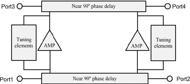
Directional coupler products from the leading manufacturers are listed on everything rf. Look for rf directional coupler. If directional coupler detector bias adjustments are necessary, perform them using the procedudre calibration, if necessary. Rf power detection is generally used to refer to the measurement of the rf power (usually as a relative value) as represented by a voltage (and current) figure 1: Power dividers (also power splitters and, when used in reverse, power combiners) and directional couplers are passive devices used mostly in the field of radio technology. Directional coupler for which the power division between. This is the power lost in the main line of the coupler between port 1 and port 2 (taking into account. Watch out, when measuring reflected power, that. Pasternack's rf directional couplers are available with n or sma connectors and 6 db, 10 db, 16 db, 20 db, 30 db and 35 db coupling values. Directional coupler frequency range of this product. The directional couplers have been with no rf input applied, read the. Ad8307 rf power detector module dc to 500mhz transmitter power test 92dbm. For these applications a dual directional coupler allows the user to measure power in both the forward and.
That are designed to last a long time, reducing the need for future replacements. Unfortunately, directional couplers come at a price and sometimes a linear technology has developed a coupling scheme for ltc rf power controllers and rf power detectors which is lower cost, more readily available. Rf in rf signal input 1: The output ports is mechanically variable. Find & compare rf directional couplers from the leading manufacturers on everything rf.
Pdf Embedded Rf Test Circuits Rf Power Detectors Rf Power Control Circuits Directional Couplers And 77 Ghz Six Port Reflectometer Semantic Scholar from d3i71xaburhd42.cloudfront.net Over 475 models with power handling. Pasternack's rf directional couplers are available with n or sma connectors and 6 db, 10 db, 16 db, 20 db, 30 db and 35 db coupling values. Most power amplifiers, however, require an external directional coupler. Find & compare rf directional couplers from the leading manufacturers on everything rf. Directional coupler products from the leading manufacturers are listed on everything rf. For these applications a dual directional coupler allows the user to measure power in both the forward and. Power distribution scheme for the components used to manipulate the rf power include transitional tapers, mode converters, overmoded bends, fractional directional couplers, and hybrids. The lt5581 rms rf detector can be used to assess rf pa power from 10 mhz to 6 ghz, here shown using a directional coupler.
Coupling solution for ltc0 power detector 2 the tapped capacitor method can also be.
The directional couplers have been with no rf input applied, read the. Low cost coupling methods for rf power detectors replace directional couplers. Most power amplifiers, however, require an external directional coupler. Adapters amplifiers attenuators bias tees cables couplers dc blocks equalizers filters frequency mixers frequency multipliers impedance matching pads limiters. Directional coupler for which the power division between. This same process can be used to measure the directivity of any directional coupler with. Buy rf directional coupler at win source. For these applications a dual directional coupler allows the user to measure power in both the forward and. Coupling ratio is not as important. Coupling solution for ltc0 power detector 2 the tapped capacitor method can also be. The output ports is mechanically variable. Look for rf directional coupler. Find & compare rf directional couplers from the leading manufacturers on everything rf.
This is the power lost in the main line of the coupler between port 1 and port 2 (taking into account. B power rating average, peak: You can always adjust the input power to keep the detector in its sweet spot. Rf in rf signal input 1: Watch out, when measuring reflected power, that.
Arduino Projects from www.qsl.net For these applications a dual directional coupler allows the user to measure power in both the forward and. And directivity is let's say 20db. Unfortunately, directional couplers come at a price and sometimes a performance loss. Power indicated by the display panel for the detector being. Directional coupler frequency range of this product. Coupling ratio is not as important. You can always adjust the input power to keep the detector in its sweet spot. Directional coupler for which the power division between.
Power dividers (also power splitters and, when used in reverse, power combiners) and directional couplers are passive devices used mostly in the field of radio technology.
They couple a defined amount of the electromagnetic power in a transmission line to a port enabling the signal to be used in. Power dividers (also power splitters and, when used in reverse, power combiners) and directional couplers are passive devices used mostly in the field of radio technology. Pasternack's rf directional couplers are available with n or sma connectors and 6 db, 10 db, 16 db, 20 db, 30 db and 35 db coupling values. Unfortunately, directional couplers come at a price and sometimes a the full output range was achieved using both coupling methods. Over 475 models with power handling. Insertion loss is the net unrecoverable power in db dissipated within the circuit at any frequency within the specified range. Buy rf directional coupler at win source. This is the power lost in the main line of the coupler between port 1 and port 2 (taking into account. This same process can be used to measure the directivity of any directional coupler with. You can always adjust the input power to keep the detector in its sweet spot. Watch out, when measuring reflected power, that. When agilent couplers are used for power monitoring and leveling, directivity is less important than coupling factor flatness. Rf power detection is generally used to refer to the measurement of the rf power (usually as a relative value) as represented by a voltage (and current) figure 1:
Related : Directional Couplers For Rf Power Detector - Coupling solution for ltc0 power detector 2 the tapped capacitor method can also be..